Bosch radar retrofit
Retrofitting an AP-era Tesla Bosch radar to pre-AP Model S — parts, mounting, wiring to chassis CAN, VIN learning, GTW emulation, and winter caveats.
Updated June 11, 2026
Pre-AP Model S shipped without forward radar. Adding the Bosch radar that AP1 cars used gives NAP real radar tracking — up to 32 detected objects simultaneously instead of vision-only estimation — and significantly improves the smoothness and accuracy of adaptive cruise. The radar retrofit is optional but it is the biggest single improvement to longitudinal control you can make.
What it adds
Without radar, NAP estimates lead-car distance and relative speed from the front camera alone. The delay in that estimate is 1–2 seconds. With the Bosch radar, NAP receives direct radar measurements of distance, lateral offset, relative velocity, and lateral relative velocity for up to 32 objects at 100 Hz. Adaptive cruise following becomes more precise and responds earlier to changes in traffic.
The radar hardware
The radar Tesla used on early AP1 cars is the Bosch MRRevo14, also referred to by part numbers 1038224-00-A, 1038224-00-B, and 1057551-00-B. The same radar hardware was used by Honda, Nissan, VW, Audi, and others; Tesla is unusual in reading raw object data from it rather than letting the radar firmware decide when to brake.
The 1038224-00-B variant includes a heater element that melts snow and ice buildup on the radome. The 1038224-00-A does not. If you're in a climate with significant winter weather, the B variant is worth seeking out.
Radar units come from AP1 Model S salvage. Used units run about $85–150 on eBay, which is where most of the community got theirs — search the part numbers above. Salvage yards work too. Range is approximately 160 m (525 ft) longitudinal; the short-range beam has a lateral cone of roughly 45°.
You will also need:
- A mounting bracket — the established design attaches behind the nosecone, using the existing holes in the front bumper structure and relocating the front 12 V post.
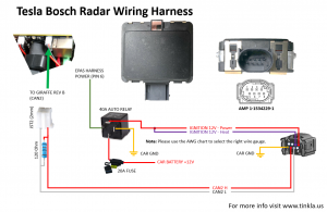
- A wiring harness — power from fuse F75 in the frunk fuse box, ground to the left frunk ground post, and a CAN twisted pair running from the radar back to the passenger compartment where it connects to the harness.
There is no off-the-shelf kit — you assemble the pieces yourself. The harness most of us use comes from AliExpress.
Mounting position
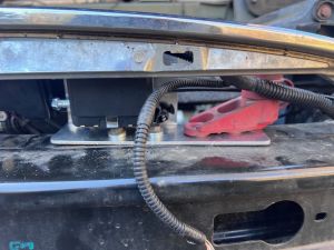
The radar mounts behind the nosecone, centered on the front of the car. The bracket design replaces the 12 V jump-post mount; you relocate the post to studs on the bracket and secure the radar to the front bumper structure using 5 mm black screws and split-lock washers.
If you have a 3D printer, there's a printable radar mount on Thingiverse that does the job. Print it in ABS or ASA — the nose of the car gets hot, and the mount needs to survive it. Some people have used PETG, but it softens with heat and isn't suited to living behind a black bumper in the sun; consider it only if your climate looks like Norway or Antarctica.
The radar faces forward through the nosecone. Key installation note: the existing front wiring harness (parking sensors, front lights) must run over the back of the radar connector, not behind it — any metallic element behind the radar will degrade detection.

Wiring
The radar harness has three connections:
- Power: an add-a-fuse tap to fuse F75 in the frunk right-side fuse box. Pull F75, insert it in the provided fuse tap's secondary slot, and install the tap in F75's location.
- Ground: a ring terminal to the dedicated ground post behind the radar in the frunk area — take the nut off, install the ring, retighten.
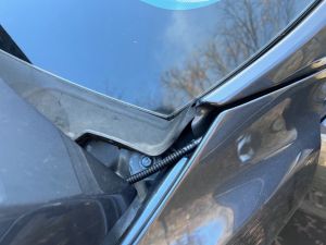
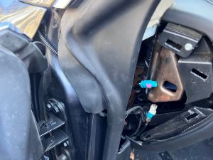
- CAN: a twisted-pair cable (CAN High / CAN Low) running from the radar connector through the front fender, under the door seal, and into the cabin. There is typically a hole in the door seal gasket area to route through; your mileage may vary by build. Route it to the OBD2 port area and connect to the CAN1 (JST 2.54 mm) expansion port on the OBD-C adapter.
A 120 Ω termination resistor between CAN+ and CAN− is required on the radar's CAN connection. The harnesses sold for this purpose typically include it built in.
Use twisted-pair cable for the CAN run. The community recommendation is Belden 8723 or equivalent shielded twisted pair.
Terminating at the adapter
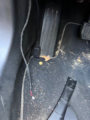
The cabin end connects to the adapter's CAN1 port, which is a JST 2.54 mm connector. The AliExpress harness doesn't come with one fitted, so you have two options: solder a JST 2.54 connector onto the harness leads (the clean way), or do what Dagger did — strip the leads, seat them directly onto the JST pins, and wrap the joint in electrical tape to hold them. Not elegant, but it makes solid contact and it's how at least one daily-driven install runs today.
If you're not sure which wire is which at the cabin end, find out with a multimeter in continuity mode: put one probe on a pin in the radar-side connector, touch the other to each lead at the cabin end until it beeps, and label the wire. Map each lead back to the radar connector's CAN High and CAN Low positions and match them against the harness diagram above — CAN polarity matters, and swapping High/Low means the radar stays silent.
If you get stuck, ask in the Discord — someone there has almost certainly done this exact install and will lend a hand, though don't expect them to build your harness for free.
NAP settings for radar
In the NAP settings panel, enable radar and configure:
- Radar enabled (
NAPRadarEnabled): turn this on. - Radar behind nosecone (
NAPRadarBehindNosecone): set this if your radar is in the nosecone position (the standard mount). This controls how the GTW emulation layer (see below) encodes position to the radar. - Radar offset (
NAPRadarOffset): lateral offset in meters from the car centerline to the center of the radar. Zero if the radar is perfectly centered. Positive = toward driver side.
VIN learning procedure
Salvage radars are locked to the VIN of the car they came from. The radar will respond for the first 5 seconds after power-up regardless, but it will stop updating object data after that unless it receives messages matching its programmed VIN, EPAS type, and mounting position.
To re-program the radar to your car, run the Radar VIN Learn procedure from the NAP settings panel:
- With the radar installed and connected, turn the car on (Park, foot on brake).
- In the NAP settings panel, scroll to the radar section and press Radar VIN Learn.
- Follow the on-screen confirmation. The process communicates with the radar over CAN and reprograms it with your car's VIN, the EPAS type setting, and the position setting.
- When complete, let the car go to Car Off mode, then reboot the comma device.
After VIN learning, the radar should continuously stream data. If it stops after 5 seconds, the EPAS type or position values don't match what the radar expects from its donor car — see the troubleshooting section below.
GTW emulation
The Bosch radar was designed to operate in a Tesla CAN network where it receives messages from several real ECUs — particularly the Gateway (GTW), which provides vehicle speed, steering angle, gear state, and other signals the radar uses for object tracking. None of those ECUs exist on pre-AP Model S in the form the radar expects.
NAP handles this by having the panda impersonate the Gateway ECU on the radar's CAN bus. The rx_all hook in tesla_preap.h intercepts every CAN frame on the chassis bus and rewrites or forwards the ones the radar needs, including encoding the radar position into the forwarded messages when RADAR_BEHIND_NOSECONE is set. This gateway emulation runs transparently — the radar believes it is in a stock AP1 car receiving normal GTW traffic.
Troubleshooting radar communication
The TeslaRadarAlertMatrix message (CAN ID 0x501 on bus 1) contains a bitmap of every error the radar is reporting. The two most common issues during initial setup:
RADC_a062_strRackMismatch— EPAS type mismatch. The EPAS type value sent during VIN learn does not match the donor car. Values: 0 = Bosch L538, 1 = Bosch L405, 2 = Mando FGR64, 3 = Mando VGR66, 4 = Mando VGR66 Gen3. For pre-facelift AP1 donor cars, 0 or 1 are most common.RADC_a061_radPositionMismatch— Position mismatch. Values: 0 = Model S pre-facelift, 1 = Model S post-facelift, 2 = Model X. Use the donor car's VIN (not yours) to determine the right value — 2014–2015 Model S is always 0, 2017+ Model S is always 1, 2016 Model S could be 0 or 1 depending on build month.
Use Cabana to monitor the TeslaRadarAlertMatrix message if you need to diagnose errors beyond the initial VIN learn.
Winter and dirt caveats
The radar's radome (the plastic face) must be kept clean. Heavy mud or snow accumulation on the front of the car will degrade or block the radar signal. The 1038224-00-B variant's heater element helps with ice and light snow, but it does not clear heavy buildup.
Tinkla had a toggle to ignore radar errors in winter. NAP currently does not — if the radar reports persistent errors from snow or mud buildup, clean the nose of the car.
When reinstalling the nosecone after radar work, make sure the parking sensor harness does not end up in front of the radar.